HR-SMAPS1001/2 Mechatronic Ku-band Phase Shifter
Device Overview
1.1 Features
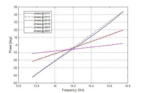
● Highly linear phase
● Very low insertion loss
○ < 0.2dB @ 0111
○ < 0.5dB @ 0010
○ < 1.0dB @ 0001
● Delay range
○ 30-250ps through-mode note1,3
- for 500MHz passband
○ 15-140ps reflective-mode note 2,3
- for < 3GHz passband and <0.5dB loss
● Bit resolution
○ 5bits as standard
- up to 7bits possible
● Highly constant delay
○ THROUGH-MODE (HR-SMAPS1001)
- ±25ps within 10% passband for absolute value of time delay <250ps smaller time delays will have less variation
○ REFLECTIVE-MODE (HR-SMAPS1002)
- ±2ps within 10% passband
● switching-time for 1LSB
○ < ~30ms
- two use-cases –
■ static – zero-power hold option for very low average power drain
■ dynamic – switching-time can be optimized further
● Mechatronic - Shape Memory Alloy (SMA) actuated - electronic control
○ lightweight
○ small size
○ high reliability
● Small size envelope
○ half wavelength to 3/4 wavelength
● potential for dual polarized operation, particularly in REFLECTIVE-MODE (HR-SMAPS1002), but THROUGH-MODE (HR-SMAPS1001) is also possible;
○ allows possibility of polarisation control transformation on a per-element basis; (i.e. each element of array can perform polarisation adaptation note 4
● Very small temperature dependence
○ typically ~30ppm (Metal and FR4 components)
○ possibility for temperature stabilization
● power consumption
○ with duty cycle 10%
- 6mW per phase shifter
- <10W per antenna array of 1000 phase shifters
○ with 100% duty cycle
- <60mW per phase shifter
An IMPORTANT NOTICE at the end of this data sheet addresses availability, warranty, changes, use in safety critical applications, intellectual property matters and other important disclaimers.
PRELIMINARY DATA.
Projected Performance Data -Through-Mode (HR-SMAPS1001)

2.1 Phase vs Frequency

2.2 Insertion Loss vs Frequency

2.3 Delay vs Frequency
Projected Performance Data REFLECTIVE-MODE (HR-SMAPS1002)

3.1 Delay vs Frequency


4 Notes
1. THROUGH-MODE plots are for phase-shifter (HR-SMAPS1001) with separate input and output ports
2. REFLECTIVE-MODE plot is for phase -shifter (HR-SMAPS1002) with single port: input wave is reflected back through same port with controlled amount of delay.
3. In both cases (HR-SMAPS1001/2) we can offer dual polarised operation; i.e. the phaseshifter can independently work with signals of two orthogonal polarisations with very little cross-coupling between them.
4. A future development will allow dynamic control of the polarisation of the signal
5. Traditional phase-shifters are characterised by phase / dB, a figure of merit. The devices presented here have very low losses, so this will be very high.
a. However, when regarded as devices producing a true time delay, the
THROUGH-MODE device produces higher losses for greater delay times, and a narrower passband.
b. The REFLECTIVE-MODE device gives lower figures for true time delay in exchange for extremely low losses, typically on the order of 0.08 -0.25dB, and significantly wider passband.
PRELIMINARY DATA